Once commissioned, the most meaningful gains come from operating strategy—how the drive interacts with the plant or airside system.
Chilled Water Pumps
Control on differential pressure at the hydraulically remote point, not at the pump discharge.
Reset DP setpoint down during low load periods to minimize pump horsepower.
Maintain a minimum speed high enough to avoid dead‑heading or control valve instability.
Condenser Water Pumps and Cooling Tower Fans
Reset condenser water temperature based on outside wet‑bulb and chiller performance curve.
Coordinate tower fan speed and bypass valve positions; avoid situations where the tower is fighting itself (e.g., full bypass with high fan speed).
For multi‑cell towers, favor more cells at lower speed rather than a single cell at high speed to improve heat rejection per kW (subject to freezing and plume constraints).
AHU Supply and Return Fans
Use duct static pressure resets based on VAV box damper positions—the classic 30% “most open damper” method reduces fan energy by lowering the static target as boxes open up.
Avoid static pressure sensors near turbulent sections; place them in a representative location with straight duct upstream.
Verify building pressure control sequences won’t cause the return fan to hunt the supply fan.
Maintenance That Prevents Failures
The best VFD maintenance is routine, simple, and well‑documented.
Cooling path: clear vents and filters; confirm fans are operating.
Connections: torque‑check power and ground lugs; inspect control wiring strain relief.
Event history: review fault logs and trends for nuisance trips or thermal warnings.
Annual Tasks
Pull a parameter backup, compare to the baseline, and re‑archive.
Inspect motor insulation resistance if the application is critical or long‑cabled.
Validate BAS points (command, status, speed) and sensor calibration used for the control loop.
Symptoms to Act On Immediately
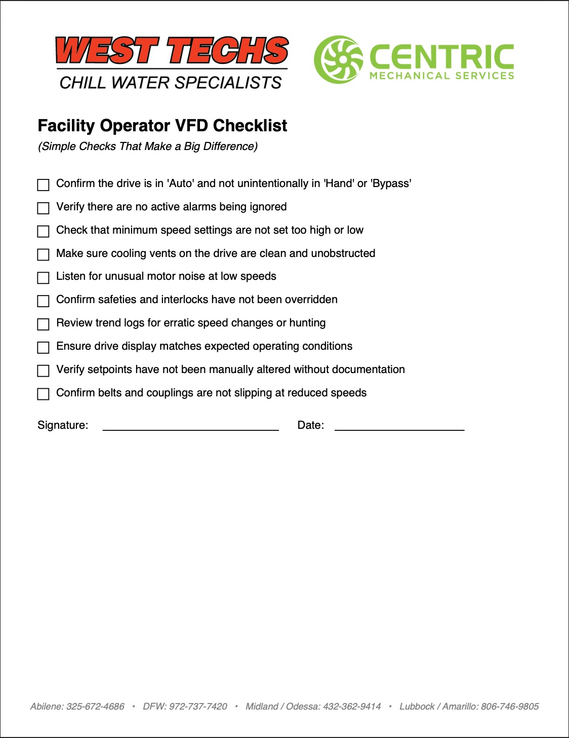
Unusual motor noise at low speeds (possible resonance or bearing issue).
Erratic speed changes without corresponding load changes (PID tuning, sensor drift, or overrides).
Rising drive heatsink temperature or frequent over‑temp warnings (blocked airflow or failing fans).
Bypass indicators lit after a service event (someone left the system in bypass).
Measuring What Matters: KPIs for VFD Performance
If you can’t quantify performance, you can’t optimize it. Track these KPIs to confirm your drives are delivering:
Average speed vs. time (by mode/season): Lower average speeds should correlate with lower kWh.
kW per CFM (fans) or kW per GPM (pumps): Normalize energy to delivered work.
Setpoint tracking error: Are loops steady, or do you see oscillations?
Alarm rates: Nuisance faults and overrides point to deeper control issues.
Maintenance deltas: Bearing replacement intervals, belt life, seal failures—should improve when speeds and starts are gentler.
Tie these metrics back to monthly utility bills and demand charges to quantify savings.
Specifying and Procuring VFDs: Practical Considerations
When adding or replacing drives, look beyond faceplate horsepower:
Environmental rating: NEMA 1 vs. 12 vs. 3R or better if outdoors; space heaters for damp locations.
EMC and harmonics: For facilities with many drives, specify appropriate line reactors, harmonic mitigation, or facility‑wide harmonic compliance strategies.
Motor lead length: If runs are long, require dV/dt or sine‑wave filters to protect motor insulation.
Integrated bypass: Decide whether you need a 3‑contactor bypass (with test position) and how it will alarm.
BAS integration: Confirm analog/digital I/O, network protocols (BACnet/IP, BACnet MS/TP, Modbus), and which points will be monitored.
Serviceability: Access to fuses, fans, boards; availability of local parts and support; clear labeling and parameter export capability.
Troubleshooting Playbook (When Things Don’t Behave)
If a VFD‑controlled system is unstable, approach it methodically:
Confirm the Basics
Is the drive actually in Auto and being commanded by the BAS?
Are there active alarms or pending trips?
Was bypass engaged or an override left in place?
Check the Process Variable
Validate the sensor (pressure transducer, flow meter) reading with a calibrated gauge.
If the sensor is wrong, the loop will never stabilize.
Review Minimums and Limits
A minimum speed too high can cause control valves or dampers to “pinball.”
Excessively low minimums can starve flow and trigger safeties.
Tune the Loop
Reduce proportional gain if the system overshoots.
Add integral slowly to eliminate offset without causing oscillation.
Consider a deadband or setpoint reset strategy to avoid constant micro‑adjustments.
Look for Mechanical/Electrical Contributors
Slipping belts or couplings at reduced speed.
Cavitation in pumps if NPSH is marginal at lower speeds.
Supply fan resonance at certain frequencies—use skip frequencies to jump past trouble bands.
Safety and Compliance Notes
Always lock out/tag out before working inside a VFD enclosure. DC bus capacitors retain charge after power off—observe the manufacturer’s discharge time.
Maintain clearances and ventilation around drives per the installation manual. Heat is the silent killer of power electronics.
For life‑safety integrations (e.g., smoke control), verify the sequence of operations with local code requirements and test it under witness when required.
Lifecycle Economics: Beyond First Cost
A VFD project’s ROI isn’t just energy savings versus capital. Factor in: